
In electrical resistance strain gauge the displacement or strain is measured as a function of resistance change produced by the displacement in the gauging circuit.
When the conductor is stretched, its length will increase and area of cress section will decrease this will result in change in resistance. Change in resistance per unit strain is defined as Gauge Factor.
Types of electrical resistance strain gauges
Electrical resistance strain gauge with metallic sensing element may be broadly classified in to four groups.
       a. Un-bonded wire strain gauge
       b. Bonded wire strain gauge
       c. Foil strain gauge
       d. Weldable strain gauge
The principal of the un-bonded metallic strain gauge is based on the change in electrical resistance of a metallic wire due to the change in the tension of the wire. This type consists of a stationary frame and a movable platform. Fine wire loops are wounded around the insulated pins with pretension. Relative motion between the platform and the frame increases the tension in two loops, while decreasing tension in the other two loops. These four elements are connected approximately to a four arm Wheat stone bridge. These type strain gauges are used for measurement of acceleration, pressure, force etc.
 2.2.2 Bonded Wire Strain Gauge :
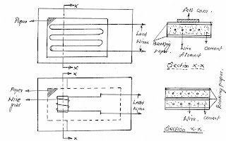
 2.2.4 Weldable Strain gauge:
2.3 Optical strain gauges
The optical strain gauges are used to measure elongation as well as deflection, following are the two type of optical strain gauges,
a. Marten’s optical gauge2.3.1. Marten’s optical gauge:b. Tuckerman Optical Gauge
These optical stain gauges employs variety of mirror systems to obtain optical magnification.
The well known optical system used in a strain gauge on a single mirror system is marten’s optical gauge.
The pivoted knife edge carries a mirror and the other end of this arm is fastened to specimen as the specimen elongates the measuring knife edge will rotate about its point there by tilting the mirror. The Reflection of the illuminated scale in this mirror is viewed through the telescope.
 2.3.2 Tuckerman Optical Gauge:
In this instrument, the relative rotation between the fixed mirror and the movable mirror is measured with autocollimator. The autocollimator consists of a lamp source to produce parallel beam of rays and a scale to measure the deflection of the reflected ray.
A tungsten carbide rocker (lozenge) acts as a moving knife; one face of this lozenge is polished to act as a mirror.
If the specimen deforms, rotates the lozenge which in turn deflects the incident ray back to the reticule. Actually three images are visible on the reticule one gives the measurement of strain and other two helping alignment of the gauge. The sensitivity of the gauge is 2 micro strains and this gauge is available with a wide range of gauge length of 6mm. it can measure both static and dynamic strains and cyclic strains up to 180 Hz.

2.4 Pneumatic strain gauge :
The principal of operation of a pneumatic gauge depends upon the relative discharge of air between a fixed orifice and a variable orifice.
Magnification up to 100,000 times and the gauge length as small as 1mm are possible to achieve by these gauges.
These gauges are suitable for both Static and dynamic strain measurements. These are sensitive, robust and reliable.

2.5. Acoustic strain gauge :
In an acoustic strain gauge the variation in length of a wire stretched between two gauge points is measured which alters the natural frequency of the wire.
The magnitude of frequency change for a strain gauge can be increased by decreasing the length of the wire or stress in wire.These gauges are highly accurate and long term reliable. Optical strain gauges are used to measure strains in concrete structure, concrete dams, rock, steel structures etc.


